
Line Output Converter Installation Guide
Connect SKAR2CH-LOC and SKE2LOC to a verified factory speaker signal: model-specific wiring, power, turn-on, RCA outputs, levels, and troubleshooting.
On this page
Use a line output converter (LOC) when a factory radio or factory amplifier supplies a suitable speaker-level signal and the aftermarket amplifier needs RCA input. This guide covers SKAR2CH-LOC and SKE2LOC. They have different power and turn-on connections; identify your model before wiring.
Before connecting either model
- Use a verified wiring diagram for the exact vehicle, radio, and factory amplifier. Vehicle wire colors are not universal. Have a qualified installer identify the left and right speaker-output pairs, polarity, signal range, and signal voltage.
- Choose a signal containing the frequencies your new speakers or subwoofer need. A factory tweeter output may contain little bass, and a factory subwoofer output is not a full-range source. A LOC alone does not restore missing frequencies or guarantee compatibility with every factory amplifier, active-noise-cancellation system, or speaker-detection circuit.
- Compare the measured source signal with the exact converter's published input limits. Never apply battery power to a speaker-input lead, join left and right outputs together, or treat a speaker negative lead as chassis ground.
- Follow the vehicle manufacturer's shutdown and battery-disconnection procedure before splicing wires. Mount the converter securely in a dry location, insulate every connection, and route cables clear of sharp edges and moving parts.
SKAR2CH-LOC connections
The SKAR2CH-LOC converts two speaker-level channels to a left/right RCA pair. Its published maximum input is 55 watts (16 volts), with a 60-ohm load on each input channel and RCA output up to 8 volts RMS. The 60-ohm value describes the input load; it is not a resistor wattage rating or the load your subwoofer presents to the amplifier.
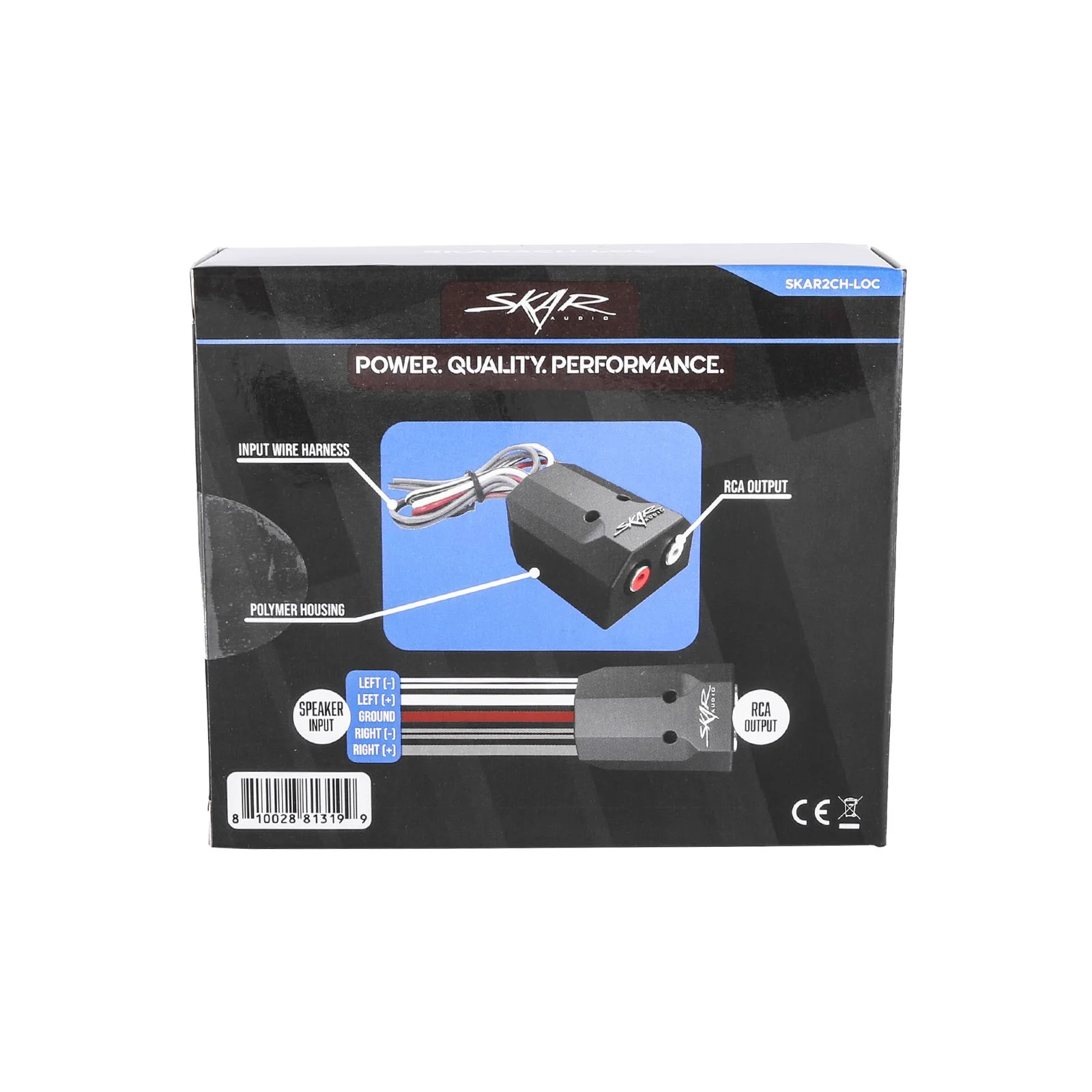
- Connect the vehicle's verified left speaker positive and negative outputs to the harness leads marked LEFT (+) and LEFT (−). Connect the verified right pair to RIGHT (+) and RIGHT (−). Preserve both channel assignments and polarity; identify the leads from the supplied diagram rather than guessing from vehicle wire colors.
- Connect the separate GROUND lead as identified in the supplied diagram to a clean chassis ground. Keep it separate from the four speaker-signal leads. This model's harness has no +12V power-input or remote-output connection; do not wire it like the powered SKE2LOC.
- Connect the white left RCA and red right RCA outputs to the aftermarket amplifier's corresponding inputs. Provide the amplifier with its own fused power, ground, and a compatible turn-on connection.
- Secure and insulate the connections. After restoring vehicle power, set the amplifier input sensitivity for the actual RCA signal. Do not assume the converter's maximum output is the correct input level for every amplifier.
SKE2LOC connections
The SKE2LOC is an active converter with separate power and ground terminals, speaker inputs, Main Output and Bass Output RCA pairs, and a supplied bass-level remote. Follow the printed labels next to each connector when inserting the removable terminal blocks.
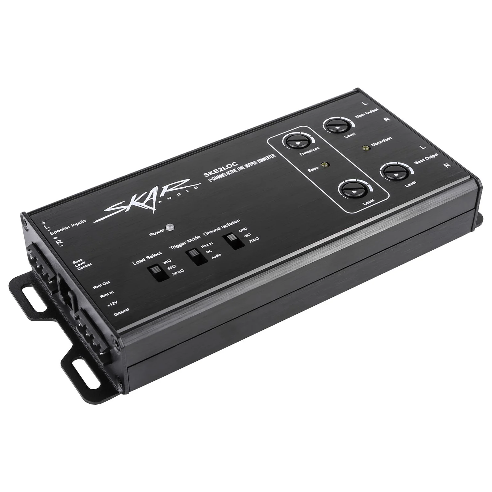
- Connect left speaker positive and negative to the L +/− speaker inputs, and right speaker positive and negative to the R +/− inputs. Keep the channels and polarities separate. These are signal inputs, not power terminals.
- Connect a properly fused positive 12V supply to +12V and a secure chassis ground to Ground. Size the supply wire and fuse to the unit's supplied instructions and the installation; do not take operating power from a speaker-signal wire.
- Choose the turn-on method that matches the installation. In Rmt In mode, connect a suitable switched +12V trigger to Rmt In. The DC and Audio positions are signal-sensing alternatives; verify reliable turn-on and shutoff with the actual factory system. Do not assume every factory signal supports either sensing method.
- Use Rmt Out for the aftermarket amplifier's remote turn-on input when that connection is suitable for the amplifier. It is a trigger output, not an amplifier power supply. Confirm the permitted trigger load before connecting multiple devices.
- Connect Main Output L/R to the amplifier inputs used for the main speakers, or Bass Output L/R to the subwoofer amplifier inputs. These outputs receive the available input signal; a bass-only factory input cannot supply missing full-range content to Main Output. Configure the amplifier crossovers for the speakers being driven.
- Connect the supplied remote and cable to Bass Level Control and mount the control within reach without obstructing driving controls or airbags.
SKE2LOC switches and levels
Load Select provides 20Ω, 60Ω, and 20kΩ positions. Choose the setting required by the verified factory speaker-output interface. These are converter input loads, not subwoofer impedance settings. Do not choose the lowest resistance simply to get more volume.
Ground Isolation is labeled GND, ISO, and 200Ω. Follow the unit's instructions for the intended grounding arrangement; this switch does not replace the Ground power connection. Diagnose the installation if noise remains instead of changing vehicle safety grounds.
Begin with output levels low and the aftermarket amplifier gain at minimum. Establish a clean source signal before adjusting Main Output or Bass Output level. The separate Bass Threshold and Level controls need to be set for the measured factory signal; there is no universal setting for every vehicle. Use appropriate test equipment and the supplied instructions, or have an installer set them. Do not use added bass or maximum gain to compensate for an unsuitable source signal.
Final checks and troubleshooting
- No sound: check that the selected factory outputs carry audio, left/right polarity is correct, RCA cables use the intended output pair, and the amplifier has power and a valid turn-on signal. On SKE2LOC, also check fused +12V, Ground, and Trigger Mode.
- Weak bass or cancellation: verify the source includes bass, both input pairs have correct polarity, and the factory processing is understood. Never join speaker negative wires to solve cancellation.
- Distortion or noise: reduce levels, check the source voltage against the converter and amplifier input limits, inspect grounding, and separate signal cables from high-current wiring. Stop if a wire or converter overheats.
- Amplifier stays on: verify the turn-on source stops when the vehicle shuts down and completes its normal sleep cycle. For SKE2LOC, confirm the selected trigger mode is appropriate before leaving the system connected.
For the speaker wiring after the amplifier, open the interactive subwoofer wiring diagrams and follow the amplifier's minimum load. See the Amplifier Installation Guide for fused power, grounding, and tuning basics.
Product references and installation help
Review the current SKAR2CH-LOC product specifications and wiring photo or SKE2LOC product specifications and labeled photos. Use the instructions supplied with your exact unit. If a label, required fuse, input limit, trigger rating, or vehicle connection is unclear, contact Skar Audio support before applying power.